
Development and experimental verification of search and rescue ROV
 0
0
Abstract
This paper presents the design of a new type of search and rescue remotely operated vehicle (ROV) system. The goal is to achieve the underwater target search and detection and small target capture and rescue operation requirements. First, the overall design of the whole underwater surface system and the layout design of the propulsion system are given. On this basis, the ROV frame structure, electronic cabin, and power cabin are designed and analyzed. To accomplish the grasping task, a grasping hand is designed based on a multifunctional manipulator to achieve underwater grasping. To make the ROV more intelligent, different kinds of underwater object detection and tracking methods are adopted and analyzed. Finally, it was tested in a pool and the sea to verify the reliability and stability of the designed search and rescue ROV.
Keywords
1. INTRODUCTION
Underwater search and rescue is one of the important tasks of intelligent maritime search and rescue [1, 2]. It is an important application field for underwater vehicles, artificial intelligent information processing, and underwater acoustic communication, as well as a multidisciplinary field for new technology. With the development of the marine economy, human activity in the ocean is increasing, which is also accompanied by more and more marine accidents, resulting in huge loss of life and property. Every year, hundreds of ships sink globally, with occasional submarine sinking and aircraft crashing into the sea, among other events. However, high seabed pressures, poor visibility and complex environments make it difficult for general equipment to complete underwater emergency search and rescue. Due to the large water area, extensive searches are extremely difficult, and only professional divers can dive to a certain depth. Professional divers' underwater vision and the ability to search for a fixed location are slightly better than that of current underwater robots. However, the particularity of such search and rescue and the complexity of underwater environment are great psychological tests for divers. Employing divers as the main search force is time-consuming, high-risk and laborious, and requires a large number of divers to work alternately in pairs or teams. In the complex and changeable ocean environment, how to reduce accidents and ensure the safety of people's lives and property are some of the key issues. Feasible and effective underwater search and rescue technology requires the development of intelligent robot system with precise control performance and full functions that can quickly search salvageable equipment to determine the cause of the accident. Joochim et al. described the design and development of a small unmanned submarine designed to explore the underwater alternative to human work[3]. The vehicle is equipped with powerful underwater probe sensors to collect underwater data, brushless DC motors for controlling direction, and real-time camera monitoring. Choi et al. designed a remote control vehicle (ROV) for visual inspection of harbor structures[4]. The ROV is equipped with a vision system, a navigation system, and a propeller for inspection tasks. The ROV can be operated manually to approach the target structure and obtain high-quality images for inspection, which provides much help for underwater harbor safety. Underwater robots are important carriers for deep-sea exploration resources and equipment, often equipped with different detection sensors for compex and dangerous underwater environments. Zhang et al. developed a 6000-meter depth rating ROV for marine scientific research[5]. With advanced technology, this ROV demonstrates the development of modern ROV equipment, making the exploration and development of deep-sea resources a reality.
Figure 1 presents the schematic diagram of an ROV searching and salvaging the target, which can be quickly deployed and recovered. The underwater robot can be continuously powered by a small generator. The operator can conduct a continuous search at a certain area from the surface, which is safe and reliable. If the ROV is entangled in rope, the diver can dive along the umbilical cord for rescue, which relieves the diver's pressure. Yue et al. put forward a new navigation and positioning system, which measures the distance through underwater acoustic communication and USBL[6]. It can be used for remote positioning and guidance of AUV to exchange information. Additionally, according to the successful experience of relevant rescue, it is preliminarily considered that it is feasible to use towed sonar to detect the range and find the suspected locations, and then use the underwater vehicle equipped with front sonar and ultra-short baseline to conduct a targeted investigation on these locations. Finally, the professional divers salvage the target.
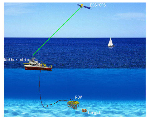
Figure 1. ROV searching and salvaging a target.
The cabled ROV designed in this project for maritime search and rescue is a new generation of micro-sized cabled ROV. The ROV features a frame structure and modular design, offering several high- and low-speed expansion interfaces. Additionally, it can be equipped with auxiliary cameras according to different demands, sonar, single function or multifunctional manipulators, underwater positioning systems, altimeters, and other sensors and tools to meet different tasks that are suitable for a variety of water environments. Figure 2 shows the 3D rendering of the small search and rescue ROV designed for this project.
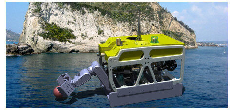
Figure 2. 3D effect diagram of search and rescue ROV.
2. DESIGN OF ROV SYSTEM FOR OFFSHORE UNDERWATER SEARCH AND RESCUE
2.1. Main specifications
The ROV system dimensions are 900 mm
Main technical specifications of the ROV system
| No | Item | Main specifications |
| 1 | Size/weight | 900 mm |
| 2 | Working depth | 200m |
| 3 | Thrust | Forward thrust > 48 kgf/lateral thrust > 30 kgf/vertical thrust > 30 kgf |
| 4 | Speed | Forward speed |
| 5 | Camera related | 2 CCD high-definition cameras, 4 30W positive LED lights |
| 6 | Sensors | Sonar, depth gauge, altimeter, electronic compass, ultra-short baseline positioning |
| 7 | Thrusters | 6 thrusters, DC150V power supply, thrust size: 17 kg/10 kg (forward/reverse) |
| 8 | Umbilical cable | 300 m |
| 9 | Power supply | 8 KW(max) |
| 10 | Control method | remotely control |
2.2. ROV surface operation box design
The surface operation part is the shore-based display. The shore-based display and control system belongs to the user interaction part. It is the core part to realize ROV information collection, display, and control. ROV communication and control [7, 8] is a key step in the design process of an ROV. Ghilezan [9] proposed a remotely controlled ROV (remotely controlled vehicle) based on the Arduino Mega 2560 microcontroller, which acquires sensor data and controls direction and acceleration. It can directly control the ROV system and display the target search and rescue scene in real time. The hardware is PC-104 (see Figure 3), and the software is a display and control system independently developed based on the C# platform. The shore-based display and control system communicates with the ROV body through the load-bearing photoelectric composite cable and directly displays the underwater camera information, the current state of the ROV body, and the underwater acoustic detection-related control and measurement data through the display and control software. In addition, it can remotely control the ROV body. The display and control software in the system integrates many functions such as comprehensive ROV control, video monitoring, remote control, and underwater acoustic positioning and tracking, with complex functions and strong pertinence, many of which are planned using label pages, with the characteristics of simple interface and convenience.
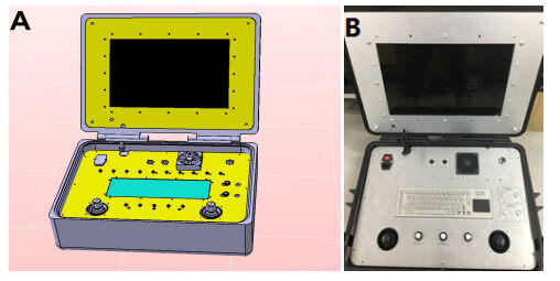
Figure 3. Design and physical drawing of the water surface control box: (A) design drawing of water surface control box; and (B) water surface control box.
2.3. Composition and principle
The ROV system consists of the ROV body, the winch (with umbilical cable system), and the surface console. Zuluaga et al. developed and implemented the low-level control system of the underwater vehicle Visor3, which is an observation ROV used to monitor and inspect port facilities and underwater structures and has been used as a test platform for developing the underwater exploration robot technology in Colombia[10]. Control and navigation algorithms are all implemented in the onboard processor (BeagleBone embedded computer). The ROV body and the surface console are important components. The ROV body and the surface console are connected by zero buoyancy bearing photoelectric composite cable, which is retracted by a hand winch. The surface console adopts the hardware architecture of an industrial computer, PLC system, manual operator, image acquisition card, industrial display, three-way switching power supply, optical terminal, switch knob, keyboard and mouse, and self-developed display and control software, which mainly performs ROV control and search and rescue capturing operations. The ROV body mainly includes an ultra-high molecular weight polyethylene (UPE) frame, upper load-bearing plate, propeller, equipment cabin (control cabin and power cabin mainly composed of PC104 system and high-power power conversion module), grab mounting and fixing mechanism, buoyancy material, acoustic detection system, sensor, sonar, camera, LED lamp, counterweight, etc., which are used to navigate and carry the detection equipment. Data communication between the above part and the underwater ROV body is realized by the optical transmitter and receiver. The system principle is shown in Figure 4.
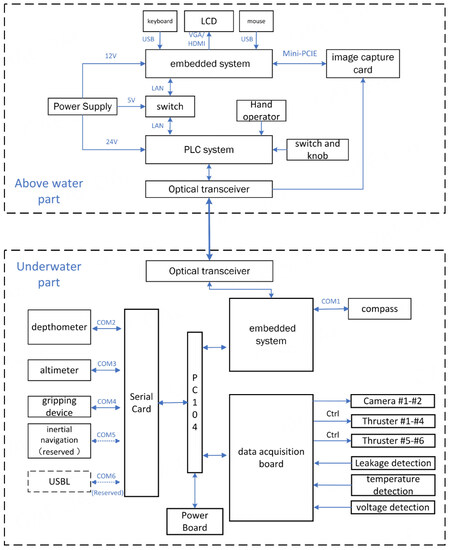
Figure 4. Display and control software interface.
The ROV system uses underwater thrusters to generate thrust, which can achieve both propulsion and steering. The layout structure of the six thrusters is shown in Figure 5, with two ascending and descending thrusters and four horizontal thrusters (the two front parts are arranged at an angle of 30
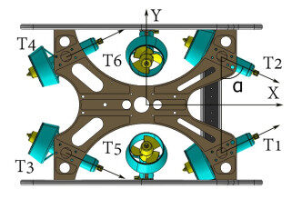
Figure 5. ROV thruster layout.
The ROV controller collects the information of peripherals (such as depth, height, attitude, compass, camera, and lighting) in real time, performs adaptive control according to the working mode, and transmits the processed relevant information to the PC-104. The PC-104 system adopts the UDP protocol and uses the optical transceiver to transmit the information in real time through the photoelectric composite cable. The ROV controller is connected to the acoustic detection system through a watertight connector. The acoustic detection system can control the working mode of the ROV (such as sink silently or fixed depth hover), cut off the power supply of the ROV, reduce the self-noise of the whole ROV system, and improve the measurement accuracy of the acoustic detection system. Photoelectric conversion is adopted between the shore-based control part and the ROV body, and reliable communication is carried out through wired photoelectric composite cable.
3. HARDWARE DESIGN OF OFFSHORE UNDERWATER SEARCH AND RESCUE ROV
The hardware part of the ROV mainly includes UPE frame, upper shell, thruster, integrated control cabin, power supply cabin, floating material, counterweight, load-bearing photoelectric composite cable (including cable retracting and releasing disc device), etc. The UPE frame is the load-bearing support of the whole ROV body, connecting and fixing each module together. The vertical thruster is mainly used to complete the diving and floating movement of the equipment, and the horizontal thruster is mainly used to complete the forward and lateral movement of the equipment. The integrated control cabin is mainly equipped with ROV control-related equipment. The power cabin mainly supplies power to each module of the equipment and has the function of independent ROV power switching to reduce the self-noise of acoustic detection. The counterweight and floating material are mainly used to adjust equipment balance and stability. The load-bearing photoelectric composite cable adopts the marine cable standard and belongs to the photoelectric composite structure, with load-bearing and tensile capacity of more than 400 kg.
3.1. ROV body framework design
h For the ROV design, structural analysis on the frame-cover structure of ROV should be carried out [11]. The overall frame of the ROV body is made of UPE with a thickness of 20 mm. The relative density of this material is lower than that of water (0.923 g/cm
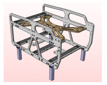
Figure 6. Frame structure diagram of the rescue ROV.
Since the force of the search and rescue ROV mainly acts on the main bearing plate, especially when the robot is hoisted, here, only the relevant finite element stress analysis of the upper bearing plate is carried out, and the static analysis software built in CATIA is used for analysis (see Figure 7). Figure 7 shows an example of the tensile force on the upper shell when the robot is hoisted. Figure 8 shows the stress–strain diagram of the frame structure. It can be seen in the figure that the design meets the allowable deformation requirements.
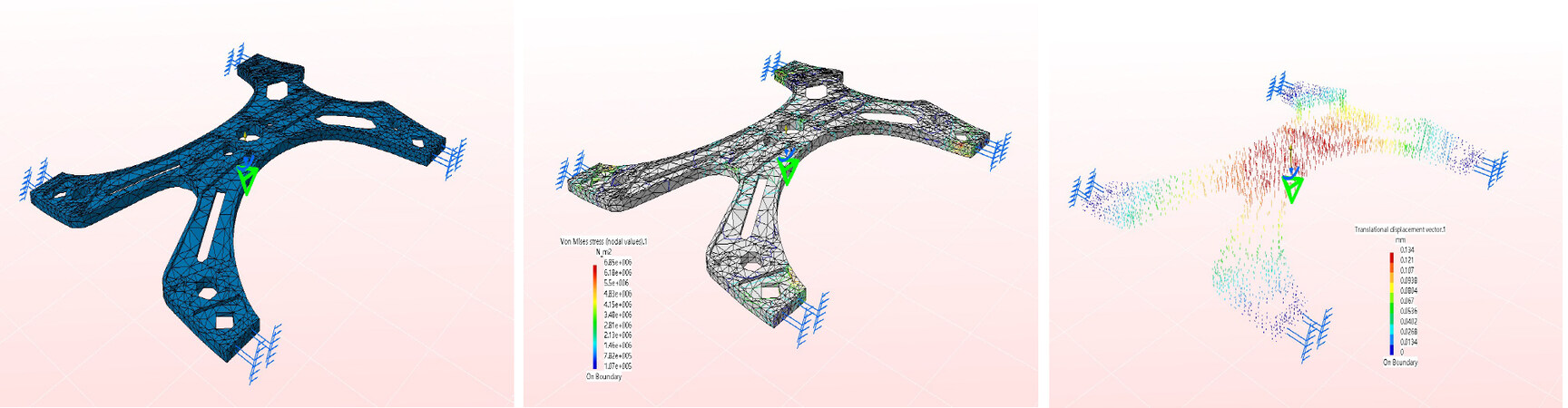
Figure 7. Static analysis of the main bearing plate.
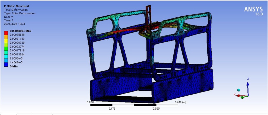
Figure 8. Analysis of ROV border deformation.
3.2. ROV electronic cabin design
This section presents the shell structure and internal support structure of the search and rescue ROV control cabin for this 200 m water depth operation, and the theoretical calculation and ANSYS finite element analysis of the strength and stability of the shell structure are carried out. This design aims to make the control cabin lighter and more compact under the constraint that it meets the safety requirements as well as lay the foundation for the actual processing and manufacturing of the ROV.
The structure of the search and rescue ROV electronic cabin is shown in Figure 9. Because the ROV electronic cabin and the power cabin are designed separately, the control cabin is mainly used to place the circuit board, which is fixed on the inner wall of the cylinder by the support rod. The separation of the electronic cabin and power cabin can better avoid the problem of strong and weak current interference. The pressing plates on both sides of the control cabin are connected with one end of the threaded flange through screws. The threaded flange is connected with the cylinder through threads, and the axial seal is realized by using double O-ring seals. The cover is integrated with the threaded flange, which is good for sealing. There is a plurality of internally threaded holes on the cover at both ends, which are used to install the propeller watertight joint, umbilical cord watertight joint, platform watertight joint, etc.
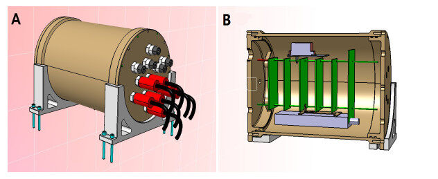
Figure 9. Electronic cabin structure design: (A) overall structure of control cabin; and (B) profile of control cabin overall structure.
The static strength analysis of the electronic cabin was analyzed by CATIA's own static analysis. The displacement and equivalent stress nephograms are shown in Figure 10.
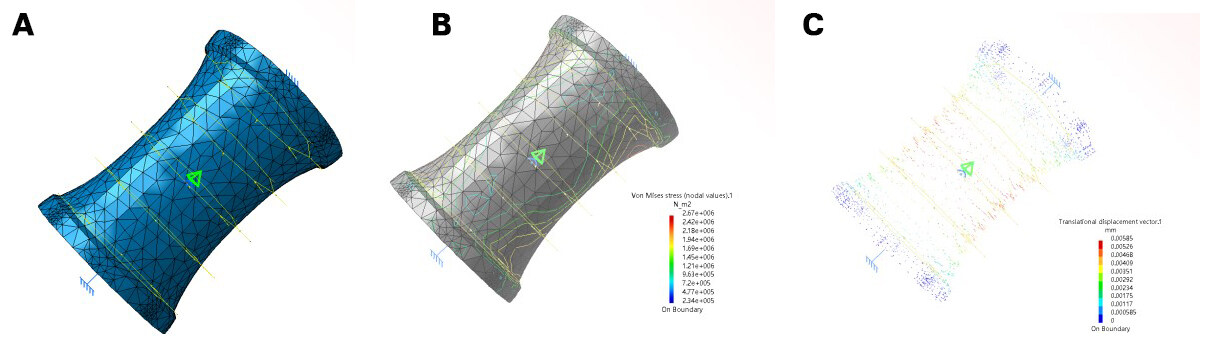
Figure 10. Static analysis of electronic cabin shell: (A) shell deformation diagram; (B) shell stress diagram; and (C) diagram of shell displacement vector.
The solid model established in CATIA was imported into ANSYS. The material properties of the model are set according to the parameters of 7075 aluminum alloy, and the solid model is modeled by the finite element method. Since there are covers at both ends of the shell, fixed constraints are imposed on both sides of the shell model and pressure is applied to the outer surface of the shell. The calculated pressure is P = 2.018 × 2 = 4.036 MPa, and the safety factor is 2. Figure 11 shows the displacement and equivalent stress nephograms in the 200 m water depth environment.
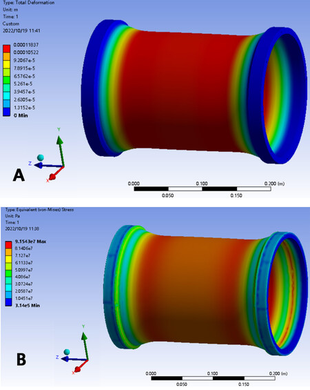
Figure 11. ANSYS static analysis of electronic cabin shell in Figure 15A and B: (A) displacement nephogram of shell static analysis; and (B) stress nephogram of shell static analysis.
3.3. ROV power cabin design
This section presents the shell structure and internal support structure of the search and rescue ROV control cabin and power cabin for the 200 m water depth operation, and the theoretical calculation and ANSYS finite element analysis of the strength and stability of the shell structure are carried out.
3.3.1. Structure design of power cabin
The power cabin (see Figure 12) is also fixed on the frame structure of the underwater vehicle through clamps. Its main function is to provide support, heat dissipation, and protection for the power distribution management module inside the cabin. Therefore, it is required that the power cabin has excellent sealing and pressure resistance, good heat dissipation design, simple structure, and easy maintenance.
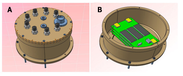
Figure 12. Design of power cabin: (A) overall structure of power cabin; and (B) internal structure of power cabin.
3.3.2. Strength and stress check of power cabin
Here, static analysis for the power cabin is conducted, and the analysis results are shown in Figure 13. Through analysis, it can be found that the designed power cabin can meet the requirement.
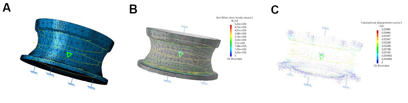
Figure 13. Static analysis of power cabin shell: (A) shell deformation diagram; (B) shell stress diagram; and (C) diagram of shell displacement vector.
3.4. ROV buoyancy material design
An underwater vehicle is a weight-sensitive structure because it requires a balance between buoyancy and gravity in the water. Composite materials with excellent specific strength and rigidity are chemically stable. In addition, the composite structure has excellent sound absorption performance. Yang et al. studied the optimal calculation process for reducing the structural weight of an autonomous underwater vehicle with an integral carbon fiber structure under prescribed conditions [12]. The buoyant material needs to work in a harsh environment of high pressure and high corrosion in the ocean for a long time. Based on its different specific working occasions, various performance index requirements are considered in the design of this article. According to the selection principle and development requirements, the high-performance sandwich material Divinycell HCP50 is selected, which features excellent buoyancy performance, high impact resistance, low water absorption, thermoformability, excellent damage tolerance, simple and fast processing, good chemical corrosion resistance, high-temperature resistance, and other characteristics. The density is 250 kg/m
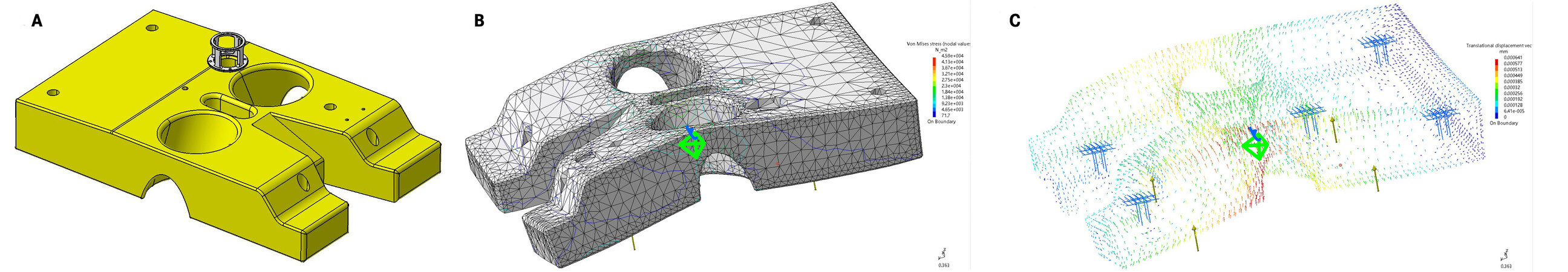
Figure 14. Design and static analysis of ROV buoyancy material: (A) design of ROV buoyancy material; (B) structure stress analysis; and (C) structural strain analysis.
3.5. ROV multifunctional manipulator grip design
The driving modes of an underwater manipulator are mainly divided into two types: hydraulic drive and motor drive. At present, most of the mature operational ROVs use hydraulic-driven underwater manipulators[13]. The main feature of the hydraulic drive is high power density, which can easily realize linear motion and rotation. However, its shortcomings are also obvious. Due to the limitation of the underwater operating environment, its dynamic control performance is not good, the control accuracy is poor, and it can easily leak oil and cause environmental pollution. Therefore, for this search and rescue ROV design, the electric manipulator mode is selected [14] considering its functionality.
Although the single-function mechanical gripper can meet simple search and rescue tasks, it is difficult to achieve some complex search and rescue tasks because there is only a single degree of freedom in opening and closing. Therefore, this design further considers a grasping scheme based on the multi-function manipulator. The mechanical gripper is the end effector of the multifunctional manipulator, which is used to complete the docking with the grasping target. The gripper is designed with a wrapping type. Figure 15 presents the design drawings of the multifunctional robotic arm gripper.
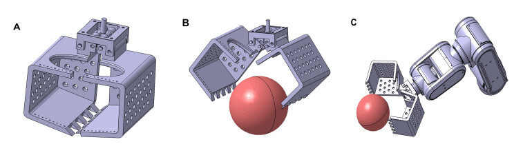
Figure 15. ROV Multifunctional Manipulator: (A) design of multifunctional manipulator gripper; (B) multifunctional manipulator grasping instructions; and (C) multifunctional manipulator grasping schematic.
3.6. ROV hardware assembly design
When the design of each part of the ROV is completed, the overall assembly design of the robot is carried out. 3D assembly design is an important part of ROV design, which can truly reflect the final product effect of ROV, simulate the assembly process, test the process matching parameters of each component, etc.Figure 16 is a schematic diagram of target grasping by a multifunctional robotic arm.
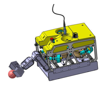
Figure 16. Grasping structure diagram of an ROV multifunctional manipulator.
4. ROV POOL TEST IN OFFSHORE UNDERWATER RESCUE
After the underwater machine prototype is assembled, a series of tests are required, which are mainly divided into indoor and outdoor tests. The indoor test mainly focuses on the power-on test of the sealed cabin to check whether the electronic components in the cabin operate normally and whether there is an alarm sound, so as to ensure the normal use of the system and test whether a single motor can operate normally and whether the overall operation can operate normally. The control board circuit in the electronic cabin was powered on to test whether the indicator light was normal to ensure that the underwater robot could move normally. Through the external frames and bottom plates on both sides, the assembly was completed with M6 screws, six thrusters, and four LED lights. The control board, processor, and power module were fixed in the electronic sealed cabin, and the expansion layer was equipped with a multifunctional manipulator.
4.1. Search and rescue ROV motion performance pool test
The premise of realizing the grasping function of an underwater robot is to test the basic functions of six degrees of freedom. It mainly tests the underwater mobility and flexibility of the underwater robot, and whether it can complete the mechanical grasping of the underwater vehicle.
The following tests were carried out: (1) The air tightness test of the manual vacuum pump was performed before launching under indoor observation for 24 h to check whether there was water accumulation in the sealed cabin and its sealing performance. (2) Switch lamp experiments were performed to check the underwater waterproofing and other functions. (3) The PTZ camera was debugged to test the stability of the platform camera and the ability to perform the up and down flip angles. (4) Whether the image transmission is normal and whether the image information can be transmitted were tested. (5) We verified the basic motion functions of the underwater vehicle in water, such as forward, backward, steering, diving, etc. (6) We verified the functions of controlling navigation and target searching and grabbing, as well as the key technical indicators, such as ROV speed, underwater search and rescue, and other specific indicators on the lake. The crane was used to lift and release the ROV, and the ROV positioning point was controlled to conduct high-speed navigation on the water surface corresponding to the location, straight driving, curved driving, turning in place, diving and floating, and directional and fixed depth navigation. The real object and test experiment of the ROV system are shown in Figure 17.
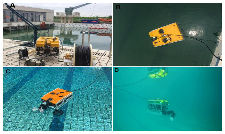
Figure 17. ROV motion performance test: (A) rescue ROV hanging; (B) ROV buoyancy and balance adjustment; (C) ROV buoyancy state test; and (D) underwater hovering state of ROV multifunctional manipulator.
4.2. Pool target search and rescue test of ROV multifunctional manipulator
Figure 18 shows the multifunctional search and rescue ROV carrying a multifunctional manipulator to search and grab underwater targets. It should be noted that, due to the limited number and placement of thrusters, pitch motion cannot be fully controlled. In the case where the ROV is used to grip a small object in this scenario, the jaw (garb system presented in Figure 15) mounted in front of the ROV will open and close, causing instability in the system, and the pitch motion cannot be fully compensated. Our solution is to retract the manipulator to run stably around the target, and then grasp it through the open manipulator. Because the manipulator actuator is electric, the center of gravity changes only slightly, and the improved PID controller can achieve a more stable control.
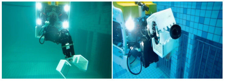
Figure 18. Underwater small target search and grasping test of ROV multifunctional manipulator.
4.3. Intelligent underwater target detection and tracking
For underwater object search and rescue, how to make the designed ROV more intelligent is an important question, and the key point is intelligent underwater target detection and tracking. For the underwater environment, there are basically two target acquisition options: optical images and sonar images. Sonar images are suitable for searching large areas, while optical images are more suitable for close-range high-precision operation scenes. Therefore, optical images acquired by underwater cameras have become the main acquisition means for underwater search and rescue. Some intelligent methods [15, 16] are applied for more intelligent underwater target detection and tracking using images. Different methods are adopted for possible object detection and tracking. Figure 19A shows the detection result with particle filter and the Hungarian algorithm method for fishes, while Figure 19B presents the detection result with the Fast RCNN method for seafood. Figure 20 presents the tracking result of an underwater vehicle, while Figure 21 shows the tracking result of moving fishes.
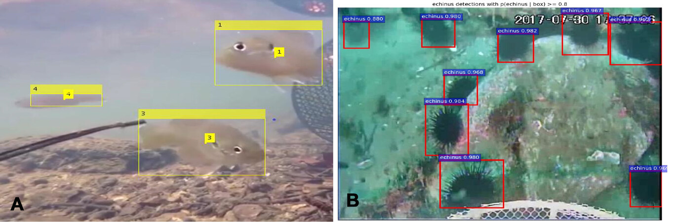
Figure 19. Detection result for fishes and seafood. (A): detection result with particle filter and Hungarian method; (B): detection result with Fast RCNN method.
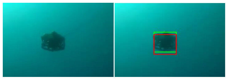
Figure 20. Tracking result of an underwater vehicle.
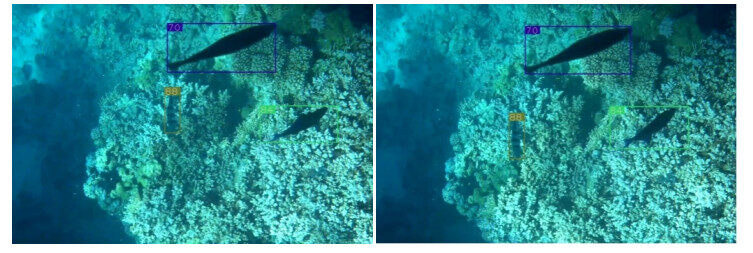
Figure 21. Tracking result of moving fishes.
5. ROV OFFSHORE TEST (TARGET SEARCH AND RESCUE)
To further verify the performance of various indexes of the developed search and rescue ROV, the research group jointly cooperated with the East China Sea Rescue Bureau to conduct the sea trial experiment. The test location was selected near the Chicken Bone Reef (122°23' E, 31°11' N) in the Yangtze Estuary. This experimental ROV was carried on the test mother ship Donghai Rescue 118. The lifting and releasing of the whole ROV were completed by the crew of the Rescue Bureau. The members of our research group were mainly responsible for the laying and control of ROV cables. Figure 22 presents the search and rescue of ROV offshore lifting and launching test. When the state was stable, sailing and diving tests were performed.
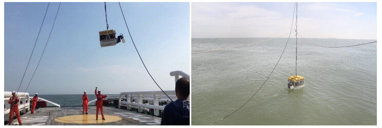
Figure 22. Search and rescue ROV is dropped into water.
When the sea condition was good (Level 2–3 sea state), the search and rescue test was carried out. The search and rescue dummy (1.1 m) was hoisted from the deck position, as shown in Figure 23. The ROV was launched to search for underwater targets. It was found that the water was turbid, as shown in Figure 24, so we changed to a surface search and rescue grab test. In this case, the target dummy was still successfully approached and grabbed, and the search and rescue task was completed, as shown in Figure 25. In the process of the sea test, it was found that the performance may degrade even when the current speed is not very high because of eddy currents and other conditions.
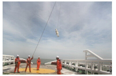
Figure 23. Search and rescue dummy hanging in the air.
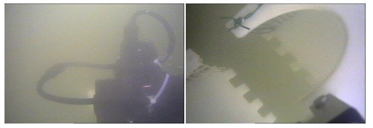
Figure 24. Underwater target search.
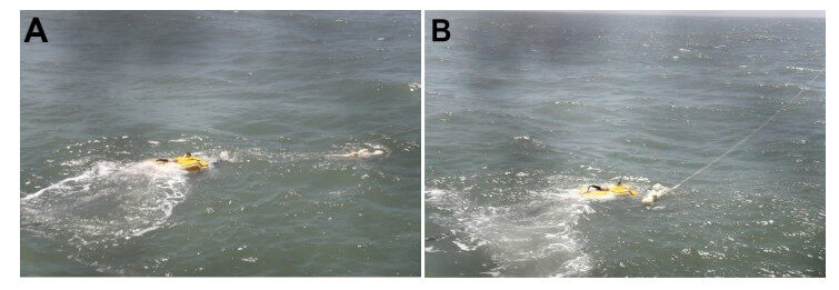
Figure 25. Underwater target search: (A) target search and rescue; and (B) ROV successfully captures the falling target for rescue.
6. SUMMARY
Based on the overall structure and frame design of the search and rescue ROV, the effectiveness of the scheme was verified. At the same time, a large margin is reserved for scenarios such as maritime search and rescue. Underwater target capture and search and rescue tests were carried out through the pool and sea test, which further verified the reliability and effectiveness of the designed ROV. To better improve the intelligence of the search and rescue ROV and reliable control in a complex environment, intelligent detection and control algorithms need further research and experimental verification in the future.
DECLARATIONS
Authors' contributions
Made substantial contributions to conception, design and experiment of the study: Sun B, Pang W, Chen M
Performed oversight and leadership responsibility for the research activity planning and execution: Zhu D
Availability of data and materials
Not applicable.
Financial support and sponsorship
This work was supported in part by the National Natural Science Foundation of China under Grant 61873161, 52271321, 62033009, U1706224, Shanghai Rising-Star Program under Grant 20QA1404200 and Natural Science Foundation of Shanghai under Grant 22ZR1426700.
Conflicts of interest
All authors declared that there are no conflicts of interest.
Ethical approval and consent to participate
Not applicable.
Consent for publication
Not applicable.
Copyright
© The Author(s) 2022.
REFERENCES
1. Cai L, Wu Y, Zhu S, Tan Z, Yi W. Bi-level programming enabled design of an intelligent maritime search and rescue system. Adv Engineer Inform 2020;46:101194.
2. Ai B, Jia M, Xu H, et al. Coverage path planning for maritime search and rescue using reinforcement learning. Ocean Engine 2021;241:110098.
3. Joochim C, Phadungthin R, Srikitsuwan S. Design and development of a remotely operated underwater vehicle. 2015 16th Int Confer Res Educ in Mechatronics (REM) 2015:148-53.
4. Choi J, Lee Y, Kim T, Jung J, Choi H. Development of a ROV for visual inspection of harbor structures. 2017 IEEE Underwater Technology (UT) 2017:1-4.
5. Zhang Q, Wang H, Li B, et al. Development and sea trials of a 6000m class ROV for marine scientific research. 2018 OCEANS-MTS/IEEE Kobe Techno-Oceans (OTO) 2018:1-6.
6. Yue Z, Wang T. Navigation and positioning system design of an AUV underwater docking. 2016 IEEE/OES China Ocean Acoustics (COA) 2016:1-6.
7. Yu C, Zhong Y, Lian L, Xiang X. An experimental study of adaptive bounded depth control for underwater vehicles subject to thruster's dead-zone and saturation. Appl Ocean Res 2021;117:102947.
8. Yu Z, Li K, Ji Y, Yang SX. Designs, motion mechanism, motion coordination, and communication of bionic robot fishes: a survey. Intell Robot 2022;2:180-99.
9. Ghilezan A., Hnatiuc M. The ROV communication and control. 2017 IEEE 23rd Int Symp Design Techn in Electr Pack (SⅡTME) 2017:336-9.
10. Zuluaga SA, Rúa S, Vásquez RE, Zuluaga CA, Correa JC. Development and implementation of a low-level control system for the underwater remotely operated vehicle Visor3. OCEANS 2016 MTS/IEEE Monter 2016:1-9.
11. Park MW, Kang JI. Structural analysis on frame-cover of USV robot. 2021 21st Int Confer Control, Autom Syst (ICCAS) 2021:1649-52.
12. Yang Z, Shen H, Su Y, Liao Y. Structure design of an autonomous underwater vehicle made of composite material. OCEANS 2014-TAIPEI 2014:1-4.
13. X Li, H Xu, C Yang, H Wang, F Yu. Study on an underwater flexible manipulator based on hydraulic drive. BATH/ASME 2020 Symp Fluid Power Motion Contr 2020: Virtual, Online.
14. Sivčev S, Coleman J, Omerdić E, Dooly G, Toal D. Underwater manipulators: a review. Ocean engine 2018;163:431-50.
15. Aminuddin NF, Tukiran Z, Joret A, et al. Hungarian-particle filtering based segmentation for on-road visual vehicle detection and tracking. 2022 IEEE 4th Global Confer Life Sci Technol (LifeTech) 2022:00-3.
Cite This Article
Export citation file: BibTeX | RIS
OAE Style
Sun B, Pang W, Chen M, Zhu D. Development and experimental verification of search and rescue ROV. Intell Robot 2022;2(4):355-70. http://dx.doi.org/10.20517/ir.2022.23
AMA Style
Sun B, Pang W, Chen M, Zhu D. Development and experimental verification of search and rescue ROV. Intelligence & Robotics. 2022; 2(4): 355-70. http://dx.doi.org/10.20517/ir.2022.23
Chicago/Turabian Style
Sun, Bing, Wen Pang, Mingzhi Chen, Daqi Zhu. 2022. "Development and experimental verification of search and rescue ROV" Intelligence & Robotics. 2, no.4: 355-70. http://dx.doi.org/10.20517/ir.2022.23
ACS Style
Sun, B.; Pang W.; Chen M.; Zhu D. Development and experimental verification of search and rescue ROV. Intell. Robot. 2022, 2, 355-70. http://dx.doi.org/10.20517/ir.2022.23
About This Article
Copyright

Data & Comments
Data
0

 Cite This Article 17 clicks

 Like This Article 0
likes
Like This Article 0
likes


Comments
Comments must be written in English. Spam, offensive content, impersonation, and private information will not be permitted. If any comment is reported and identified as inappropriate content by OAE staff, the comment will be removed without notice. If you have any queries or need any help, please contact us at support@oaepublish.com.